
- Microwave Engineering Tutorial
- Microwave Engineering - Home
- Introduction
- Transmission Lines
- Modes of Propagation
- Types of Transmission Lines
- Avalanche Transit Time Devices
- Microwave Devices
- E-Plane Tee
- H-Plane Tee
- E-H Plane Tee
- Rat-race Junction
- Directional Couplers
- Cavity Klystron
- Reflex Klystron
- Travelling Wave Tube
- Measurement Devices
- Measurements
- Example Problems
- Microwave Engineering Resources
- Quick Guide
- Microwave Engineering - Resources
- Microwave Engineering - Discussion
- Selected Reading
- UPSC IAS Exams Notes
- Developer's Best Practices
- Questions and Answers
- Effective Resume Writing
- HR Interview Questions
- Computer Glossary

Microwave Engineering - Magnetrons
Unlike the tubes discussed so far, Magnetrons are the cross-field tubes in which the electric and magnetic fields cross, i.e. run perpendicular to each other. In TWT, it was observed that electrons when made to interact with RF, for a longer time, than in Klystron, resulted in higher efficiency. The same technique is followed in Magnetrons.
Types of Magnetrons
There are three main types of Magnetrons.
Negative Resistance Type
- The negative resistance between two anode segments, is used.
- They have low efficiency.
- They are used at low frequencies (< 500 MHz).
Cyclotron Frequency Magnetrons
The synchronism between the electric component and oscillating electrons is considered.
Useful for frequencies higher than 100MHz.
Travelling Wave or Cavity Type
The interaction between electrons and rotating EM field is taken into account.
High peak power oscillations are provided.
Useful in radar applications.
Cavity Magnetron
The Magnetron is called as Cavity Magnetron because the anode is made into resonant cavities and a permanent magnet is used to produce a strong magnetic field, where the action of both of these make the device work.
Construction of Cavity Magnetron
A thick cylindrical cathode is present at the center and a cylindrical block of copper, is fixed axially, which acts as an anode. This anode block is made of a number of slots that acts as resonant anode cavities.
The space present between the anode and cathode is called as Interaction space . The electric field is present radially while the magnetic field is present axially in the cavity magnetron. This magnetic field is produced by a permanent magnet, which is placed such that the magnetic lines are parallel to cathode and perpendicular to the electric field present between the anode and the cathode.
The following figures show the constructional details of a cavity magnetron and the magnetic lines of flux present, axially.
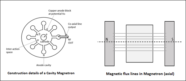
This Cavity Magnetron has 8 cavities tightly coupled to each other. An N-cavity magnetron has $N$ modes of operations. These operations depend upon the frequency and the phase of oscillations. The total phase shift around the ring of this cavity resonators should be $2n\pi$ where $n$ is an integer.
If $\phi_v$ represents the relative phase change of the AC electric field across adjacent cavities, then
$$\phi_v = \frac{2 \pi n}{N}$$
Where $n = 0, \: \pm1,\: \pm2,\: \pm \: (\frac{N}{2} -1), \: \pm \frac{N}{2}$
Which means that $\frac{N}{2}$ mode of resonance can exist if $N$ is an even number.
$$n = \frac{N}{2} \quad then \quad \phi_v = \pi$$
This mode of resonance is called as $\pi-mode$.
$$n = 0 \quad then \quad \phi_v = 0$$
This is called as the Zero mode , because there will be no RF electric field between the anode and the cathode. This is also called as Fringing Field and this mode is not used in magnetrons.
Operation of Cavity Magnetron
When the Cavity Klystron is under operation, we have different cases to consider. Let us go through them in detail.
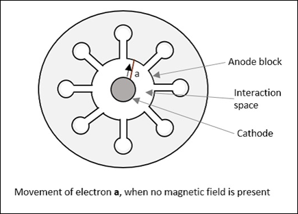
If the magnetic field is absent, i.e. B = 0, then the behavior of electrons can be observed in the following figure. Considering an example, where electron a directly goes to anode under radial electric force.
If there is an increase in the magnetic field, a lateral force acts on the electrons. This can be observed in the following figure, considering electron b which takes a curved path, while both forces are acting on it.
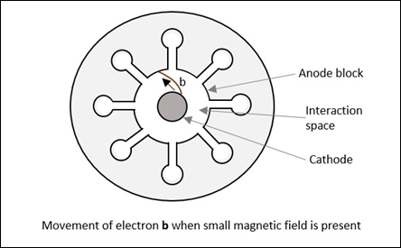
Radius of this path is calculated as
$$R = \frac{mv}{eB}$$
It varies proportionally with the velocity of the electron and it is inversely proportional to the magnetic field strength.
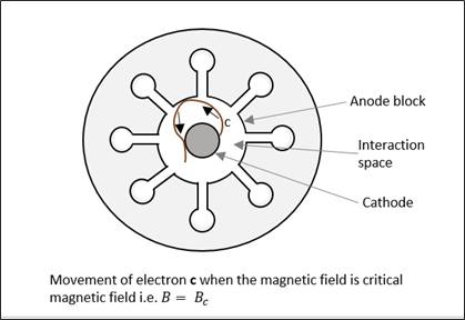
If the magnetic field B is further increased, the electron follows a path such as the electron c , just grazing the anode surface and making the anode current zero. This is called as " Critical magnetic field " $(B_c)$, which is the cut-off magnetic field. Refer the following figure for better understanding.
If the magnetic field is made greater than the critical field,
$$B > B_c$$
Then the electrons follow a path as electron d , where the electron jumps back to the cathode, without going to the anode. This causes " back heating " of the cathode. Refer the following figure.
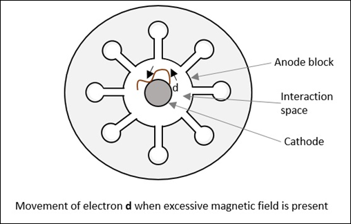
This is achieved by cutting off the electric supply once the oscillation begins. If this is continued, the emitting efficiency of the cathode gets affected.
Operation of Cavity Magnetron with Active RF Field
We have discussed so far the operation of cavity magnetron where the RF field is absent in the cavities of the magnetron (static case). Let us now discuss its operation when we have an active RF field.
As in TWT, let us assume that initial RF oscillations are present, due to some noise transient. The oscillations are sustained by the operation of the device. There are three kinds of electrons emitted in this process, whose actions are understood as electrons a , b and c , in three different cases.
When oscillations are present, an electron a , slows down transferring energy to oscillate. Such electrons that transfer their energy to the oscillations are called as favored electrons . These electrons are responsible for bunching effect .
In this case, another electron, say b , takes energy from the oscillations and increases its velocity. As and when this is done,
- It bends more sharply.
- It spends little time in interaction space.
- It returns to the cathode.
These electrons are called as unfavored electrons . They don't participate in the bunching effect. Also, these electrons are harmful as they cause "back heating".
In this case, electron c , which is emitted a little later, moves faster. It tries to catch up with electron a . The next emitted electron d , tries to step with a . As a result, the favored electrons a , c and d form electron bunches or electron clouds. It called as "Phase focusing effect".
This whole process is understood better by taking a look at the following figure.
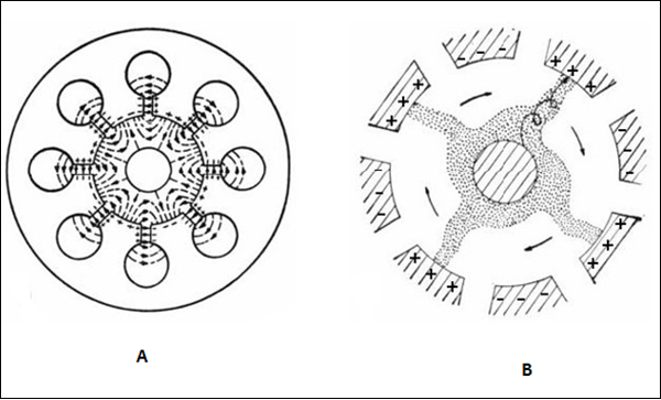
Figure A shows the electron movements in different cases while figure B shows the electron clouds formed. These electron clouds occur while the device is in operation. The charges present on the internal surface of these anode segments, follow the oscillations in the cavities. This creates an electric field rotating clockwise, which can be actually seen while performing a practical experiment.
While the electric field is rotating, the magnetic flux lines are formed in parallel to the cathode, under whose combined effect, the electron bunches are formed with four spokes, directed in regular intervals, to the nearest positive anode segment, in spiral trajectories.
To Continue Learning Please Login
Design and Simulation of 8-cavity hole-slot type magnetron in CST
Ieee account.
- Change Username/Password
- Update Address
Purchase Details
- Payment Options
- Order History
- View Purchased Documents
Profile Information
- Communications Preferences
- Profession and Education
- Technical Interests
- US & Canada: +1 800 678 4333
- Worldwide: +1 732 981 0060
- Contact & Support
- About IEEE Xplore
- Accessibility
- Terms of Use
- Nondiscrimination Policy
- Privacy & Opting Out of Cookies
A not-for-profit organization, IEEE is the world's largest technical professional organization dedicated to advancing technology for the benefit of humanity. © Copyright 2024 IEEE - All rights reserved. Use of this web site signifies your agreement to the terms and conditions.
Definition : A magnetron is a device that generates high power electromagnetic wave. It is basically considered as a self-excited microwave oscillator. And is also known as a crossed-field device .
The reason behind calling it so is that the electric and magnetic field produced inside the tube are mutually perpendicular to each other thus the two crosses each other.
Content: Magnetron
Operating principle.
- Construction
Frequency Pushing and Pulling
Disadvantages.
- Applications
A magnetron is basically a vacuum tube of high power having multiple cavities. It is also known as cavity magnetron because of the presence of anode in the resonant cavity of the tube.
The operating principle of a magnetron is such that when electrons interact with electric and magnetic field in the cavity then high power oscillations get generated.
Magnetrons are majorly used in radar as being the only high power source of RF signal as a power oscillator despite a power amplifier. It was invented in the year 1921 by Albert Hull. However, an improved high power cavity magnetron was invented in 1940 by John Randall and Harry Boot.
Here in this article, we will discuss how a cavity magnetron works. But before that, we must know how a magnetron is constructed.
Construction of Magnetrons
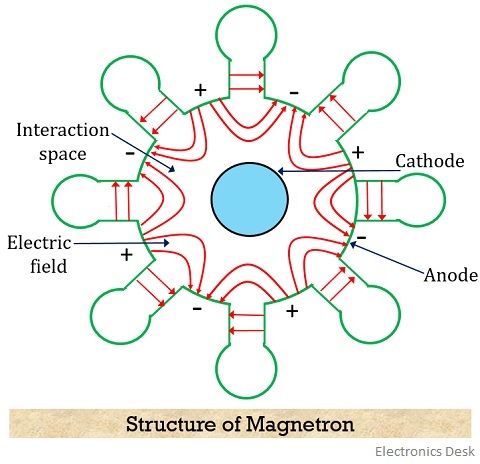
A cylindrical magnetron has a cylindrical cathode of a certain length and radius present at the centre around which a cylindrical anode is present. The cavities are present at the circumference of the anode at equal spacing.
Also, the area existing between anode and cathode of the tube is known as interaction space/region .
It is to be noted here that there exists a phase difference of 180⁰ between adjacent cavities. Therefore, cavities will transfer their excitation from one cavity to another with a phase shift of 180⁰.
Thus we can say that if one plate is positive then automatically its adjacent plate will be negative. And this is clearly shown in the figure given above.
More specifically we can say that edges and cavities show180⁰ phase apart relationship.
As we have already discussed that here the electric and magnetic field are perpendicular to each other. And the magnetic field is generated by using a permanent magnet.
Working of Magnetron
The excitation to the cathode of the magnetron is provided by a dc supply which causes the emergence of electrons from it.
Here in this section, we will discuss the working of magnetron under two categories. First without applying the RF input to the anode and the second one with the application of RF input.
1. When RF input is not present
Case I : When the magnetic field is 0 or absent
When the magnetic field is absent then the electron emerging from the cathode radially moves towards the anode. This is shown in the figure below:
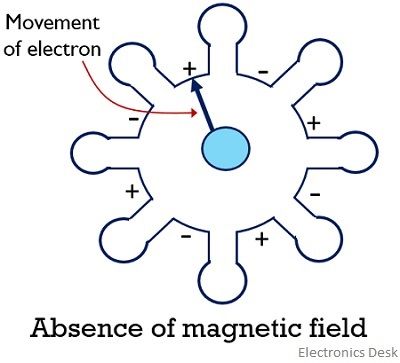
This is so because the moving electron does not experience the effect of the magnetic field and moves in a straight path.
Case II : When a small magnetic field is present
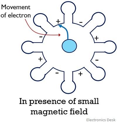
The reaching of the emitted electrons from the cathode back to it is known as back heating . So to avoid this the electric supply provided to the cathode must be cut-off after oscillations have been set up in the tube.
2. When the RF field is present
Case I : In case an active RF input is provided to the anode of the magnetron then oscillations are set up in the interaction space of the magnetron. So, when an electron is emitted from the cathode to anode then it transfers its energy in order to oscillate.
Such electrons are called favoured electrons . In this condition, the electrons will have a low velocity and thus will take a considerably high amount of time to reach from cathode to anode.
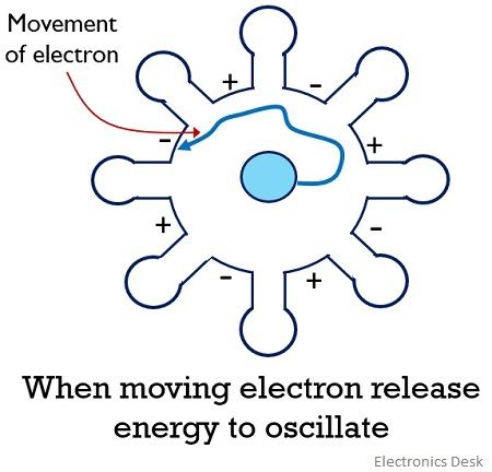
Case II : Another condition arises in the presence of RF input. In this case, the emitted electron from the cathode while travelling takes energy from the oscillations thereby resultantly increasing its velocity.
So despite reaching the anode, the electrons will bounce back to the cathode and these electrons are known as unfavoured electrons .
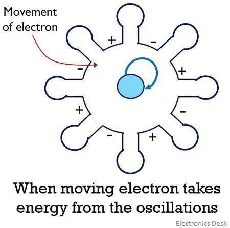
Case III : When the RF input is further increased then the electron emitted while travelling increases its velocity in order to catch up the electron emitted earlier with comparatively lower velocity.
So, all those electrons that do not take energy from the oscillations for their movement are known as favoured electrons. And these favoured electrons form electron bunch or electron cloud and reaches anode from the cathode.
The formation of electron bunch inside the tube is known as phase focusing effect .
Due to this, the orbit of the electron gets confined into spokes. These spokes rotate according to some fractional value of electron emitted by the cathode until it reaches anode while delivering their energy to oscillations.
However, the electrons released from the region of cathode between spokes, will take the energy of the field and get back to the cathode very quickly. But this energy is very small in comparison to the energy delivered to the oscillations. This is shown in the figure below:
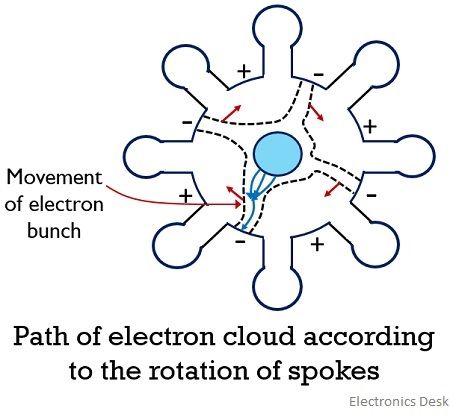
The movement of these favoured electrons inside the tube enhances the field existing between the gaps in the cavity. This leads to sustained oscillations inside the magnetron thereby providing high power at the output.
The variation in the oscillating frequency of the magnetron give rise to the term frequency pushing and pulling .
When the voltage applied at the anode of the magnetron is varied then this causes the variation in the velocity of the electrons moving from cathode to anode. This resultantly changes the frequency of oscillations.
Therefore, we can say when the resonant frequency of the magnetron shows variation due to the change in the anode voltage then it is known as frequency pushing .
The change in resonant frequency is sometimes a result of the change in the load impedance of the magnetron. The load impedance varies when the change is purely resistive or reactive. This frequency variation is known as frequency pulling . A steady power supply can provide a reduction in this frequency variation.
- Magnetrons are a highly efficient device used for generation of the high power microwave signal.
- The use of magnetrons in radar can produce radar system of better quality for tracking purpose.
- It is usually small in size thus less bulky.
- It is quite expensive.
- Despite producing a wide range of frequency, there exists a drawback in controllability of the generated frequency.
- It offers average power of around 1 to 2 kilowatts.
- Magnetrons are quite noisy.

Applications of Magnetron
- A major application of magnetron is present in a pulsed radar system in order to produce a high-power microwave signal.
- Magnetrons are also used in heating appliances likes microwave ovens so as to produce fixed frequency oscillations.
- Tunable magnetrons find their applications in sweep oscillators.
It is noteworthy here that this mode of operation of the magnetron is also known as π mode. This is so because a proper phase shift of 180⁰ is maintained between two adjacent plates. Also, it is to be noted that oscillations are only built-up in π mode.
Related Terms:
- Transmission Lines
- IMPATT Diode
- Backward Wave Oscillator
4 thoughts on “Magnetron”
Very very helpful
This is soo easy to understand Thank you
Very helpful thanks
Leave a Comment Cancel Reply
Your email address will not be published. Required fields are marked *

- Electronics
- _Digital Electronics
- _Microprocessors
- _Biomedical
- Communication
Cylindrical Magnetron Derivation
Post a Comment
Contact form.
Microwave Sources, Sensors, and Devices
Cite this chapter.

Part of the book series: Developments in Electromagnetic Theory and Applications ((DETA,volume 10))
379 Accesses
The generation of microwaves has been the main impediment to the development of microwave systems until the late 1930’s, when the first practical microwave sources were developed. Naturally, these were essentially vacuum tubes but the principles involved had to be different than those used for low frequency vacuum tubes. The limitations of interelement capacitance, for example, was one of the major problems in extending the operation of vacuum tubes to higher frequencies. The transit time of the electrons was of such orders of magnitude that it was not practical to operate beyond the lowest ranges of microwaves. The specially developed microwave tubes operate on velocity modulation of the electron beam and transition time does not play a role in these devices.
This is a preview of subscription content, log in via an institution to check access.
Access this chapter
- Available as PDF
- Read on any device
- Instant download
- Own it forever
- Compact, lightweight edition
- Dispatched in 3 to 5 business days
- Free shipping worldwide - see info
- Durable hardcover edition
Tax calculation will be finalised at checkout
Purchases are for personal use only
Institutional subscriptions
Unable to display preview. Download preview PDF.
Bibliography
S. Y. Liao, Microwave Devices and Circuits, Third edition, Prentice Hall, Englewood Cliffs, NJ., 1990.
Google Scholar
W.S. Cheung and F.H. Levien, (eds.), Microwaves Made Simple: Principles and Applications, Artech House, MA., 1985.
J.W. Lunden, “Microwave Amplifiers and Oscillators”, in Electronics Engineering Handbook, D.G. Fink, Ed., McGraw Hill Book Company, NY, 1975, pp.13–10813–13– 127.
D.G. Fink, Ed., Electronics Engineering Handbook, , McGraw Hill Book Company, NY, 1975.
D.M. Pozar, “Microwave Engineering”, Addison-Wesley, Reading, MA., 1990.
M.J. Howes and D.V. Morgan, (Eds.), “Microwave Devices”, John Wiley & Sons, London, 1976.
F.E. Gardiol, “Introduction to Microwaves”, Artech House, 1984.
E.A. Wolf and R. Kaul, “Microwave Engineering and System Applications”, John Wiley & Sons, New York, 1988.
S.F. Adam, “Microwave Theory and Applications”, Prentice Hall, Englewood Cliffs, NJ, 1969.
S. Silver and H.M. James, “Microwave Antenna Theory and Design”, IEE, London, 1984.
Book Google Scholar
T.S. Laverghetta, “Modern Microwave Measurements and Techniques”, Artech House, Norwood, MA., 1988.
G.D. Vendelin, A.M. Pavio and U.L. Rohde, “Microwave Circuit Design Using Linear and Nonlinear Techniques”, John Wiley & Sons, New York, 1990.
S. Y. Liao, “Microwave Solid-State Devices”, Prentice Hall, Englewood Cliffs, NJ., 1985.
I. Bahl and P. Bhartia, “Microwave Solid State Circuit Design”, John Wiley & Sons, New York, 1988.
W.A. Davis, “Microwave Semiconductor Circuit Design”, Van Nostrand Reinhold Co., New York, 1984.
A.F. Harvey, “Microwave Engineering”, Academic Press, London, 1963.
MATH Google Scholar
S.Y. Liao, “Microwave Electron Tube Devices”, Prentice Hall, Englewood Cliffs, NJ., 1988.
Download references
Author information
Authors and affiliations.
Department of Electrical Engineering, University of Akron, Ohio, USA
You can also search for this author in PubMed Google Scholar
Rights and permissions
Reprints and permissions
Copyright information
© 1992 Springer Science+Business Media Dordrecht
About this chapter
Ida, N. (1992). Microwave Sources, Sensors, and Devices. In: Microwave NDT. Developments in Electromagnetic Theory and Applications, vol 10. Springer, Dordrecht. https://doi.org/10.1007/978-94-011-2739-4_6
Download citation
DOI : https://doi.org/10.1007/978-94-011-2739-4_6
Publisher Name : Springer, Dordrecht
Print ISBN : 978-94-010-5215-3
Online ISBN : 978-94-011-2739-4
eBook Packages : Springer Book Archive
Share this chapter
Anyone you share the following link with will be able to read this content:
Sorry, a shareable link is not currently available for this article.
Provided by the Springer Nature SharedIt content-sharing initiative
- Publish with us
Policies and ethics
- Find a journal
- Track your research

Microwave Tubes and Circuits:
Cavity Magnetron Working : The Cavity Magnetron Working, which will be referred to as the magnetron, is a diode, usually of cylindrical construction. It employs a radial electric field, an axial magnetic field and an anode structure with permanent cavities. As shown in Figure 11-10, the cylindrical …
Crossed Field Amplifier : The Crossed Field Amplifier is a microwave power amplifier based on the magnetron and looking very much like it. It is a cross between the TWT and the magnetron in its operation. It uses an essentially magnetron structure to provide an interaction between …
Multicavity Klystron : The design of the multicavity klystron, together with all the remaining tubes described here, relies on the fact that transit time will sooner or later terminate the usefulness of any orthodox tube. They therefore use the transit time, instead of fighting it. The Multicavity …
Planar Triode Construction : Planar Triode Construction – A short transit time is essential if grid loss and noise are to be minimized, as is the reduction of internal capacitances and inductances. Also, since coaxial resonant lines and cavities are used as tuned circuits at these frequencies, …
Reflex Klystron Oscillator : It is possible to produce oscillations in a klystron device which has only one cavity, through which electrons pass twice. This is the Reflex Klystron Oscillator, which will now be described. The Reflex Klystron Oscillator is a low-power, low-efficiency microwave oscillator, illustrated schematically in …
Traveling Wave Tube Working : Like the multicavity klystron, the Traveling Wave Tube Working is a linear-beam tube used as a microwave amplifier. Unlike the klystron, however, it is a device in which the interaction between the beam and the RF field is continuous. The TWT was …
Triode Equivalent Circuit : Triode Equivalent Circuit – As frequency is raised, vacuum tubes suffer from two general kinds of problems. The first is concerned with interelectrode capacitances and inductances, and the second is caused by the finite time that electrons take to travel from one electrode …
Types of Magnetron : The Various Types of Magnetron are 20-kW Conventional Metal Ceramic Magnetron 5-MW Long Anode Coaxial Magnetron Frequency agile or Dither tuned Magnetron Voltage Tunable Magnetron The Magnetron, perhaps more than any other microwave tube, lends itself to a variety of types, designs and arrangements. Magnetrons using hole-and-slot, vane …

IMAGES
VIDEO
COMMENTS
Travelling Wave or Cavity Type. ... Construction of Cavity Magnetron. A thick cylindrical cathode is present at the center and a cylindrical block of copper, is fixed axially, which acts as an anode. This anode block is made of a number of slots that acts as resonant anode cavities. ... This Cavity Magnetron has 8 cavities tightly coupled to ...
Cavity Magnetron - Cylindrical Magnetron* Mode of OperationOperation of Magnetron#Magnetron#CavityMagnetron#CylindricalMagnetron#Microwave#MicrowaveEngineering
The 8 up to 20 cylindrical holes around its circumference are resonant cavities. A narrow slot runs from each cavity into the central portion of the tube dividing the inner structure into as many segments as there are cavities. ... this design is also-called "multicavity traveling wave magnetron" in some publications.
The cavity magnetron is a high-power vacuum tube used in early radar systems and subsequently in microwave ovens and in linear particle ... such as a klystron or a traveling-wave tube (TWT), the magnetron cannot function as an amplifier for increasing the intensity of an applied ... Spaced around the rim of the chamber are cylindrical cavities ...
cross-field effects, Magnetrons- types, 8-cavity Cylindrical Travelling Wave Magnetron- Hull cut-off and Hartree conditions, modes of resonance and PI-mode operation, o/p characteristics. HELIX TWT- types and characteristics of slow wave structures, structure of TWT and amplification process (qualitative treatment),
UNIT-IV: M-TYPE TUBES: Introduction, cross field effects, Magnetrons-different types, cylindrical travelling wave magnetron-Hull cutoff and Hartree conditions, modes of resonance and PI-mode operation, separation of PI-mode, O/P characteristics, ... The cavity resonator has the form of a volume filled with a dielectric—air, in most cases. The
A cavity resonator in a magnetron should have the dimensions of about half the wavelength of the oscillation to be generated. At 96 GHz, the wavelength is in the range of 3.125 mm. ... Typically, the first stage and the second stage are traveling-wave tubes (TWT) and the final stage is a crossed-field amplifier. Recent technological advances in ...
The 8 up to 20 cylindrical holes around its circumference are resonant cavities. A narrow slot runs from each ... "Multicavity Travelling Wave Magnetron" in some publications. Figure 2: Cutaway view of a magnetron ... Figure 7: Rotating space-charge wheel in an twelve-cavity magnetron
In this study, the design and simulation of 8-cavity hole-slot type magnetron using the electromagnetic CST software has been presented. A magnetron simulation on CST particle studio represents three configurations like as Eigen-mode, Particle Tracking and Particle in Cell (PIC) Simulation. The first simulation ensures the mode excitation whereas remaining two simulations are required for the ...
Cross-sectional schematic views of a double strapped N = 8 cavity magnetron: a the ... opposite direction to the N/2 + 1 mode but has the same non-sinusoidal radio frequency field pattern as the original travelling wave at any given moment in time. ... H.W. Welch, W.G. Dow, Analysis of synchronous conditions in the cylindrical magnetron space ...
Definition: A magnetron is a device that generates high power electromagnetic wave.It is basically considered as a self-excited microwave oscillator. And is also known as a crossed-field device.. The reason behind calling it so is that the electric and magnetic field produced inside the tube are mutually perpendicular to each other thus the two crosses each other.
Section 12.7 treats the cylindrical resonant cavity as a radial transmission line with an open-circuit termination at the inner radius and a short-circuit termination at the outer ... in describing an electromagnetic wave traveling in the + z direction, we will use the form . The form is a shortened notation for the functionE E0 exp[j( t kz)] E ...
In a travelling-wave tube amplifier (TWT) a linear electron beam interacts with the longitudinal r.f. electric field of a slow-wave structure. Approximate synchronism between the electrons and the wave on the structure is maintained over a wide band of frequencies in low power tubes using helix slow-wave structures.
24 Different Types, 8-Cavity Cylindrical Travelling Wave Magnetron T2,R4,R5 2 25 Introduction Classification, Applications T2,R3,R4,R6 1 26 TEDs - Introduction, Gunn Diode - Principle, RWH Theory, Characteristics T2,R3,R4,R6 2 27 Basic Modes of Operation, Oscillation Modes T2,R3,R4,R6 2 28 Avalanche Transit Time Devices - Introduction ...
8-Cavity Cylindrical Travelling Wave Magnetron Hull Cut-off Condition, Modes of Resonance and Pi-Mode Operation, Separation of Pi-Mode, o/p characteristics. Unit-IIIC : M-type Tubes. Aditya Engineering College (A) • In your previous courses, it is evident that devices like., vacuum tube, diode,
The Cavity Magnetron Working, which will be referred to as the magnetron, is a diode, usually of cylindrical construction. It employs a radial electric field, an axial magnetic field and an anode structure with permanent cavities. As shown in Figure 11-10, the cylindrical cathode is surrounded by the anode with cavities, and thus a radial dc ...
cylindrical-shaped cathode, the resonators blocks, the interaction region and the magnetic circuit has the main four parts of a magnetron and every individual part needs to be
Cylindrical Magnetron Derivation. A Magnetron Oscillator is used to generate high microwave power required in radar and communication systems. Magnetrons are cross field tubes in which the magnetic field and electric field are perpendicular to each other. All magnetrons consist of some form of anode and cathode operated in DC magnetic field ...
A 2D ten cavity, rising sun magnetron has been modeled using the particle-in-cell code VORPAL. Cylindrical, five-sided, and ten-sided faceted cathodes were modeled to study the variation of ...
to a multiple of 2 n. The normal mode of operation for a magnetron is the n mode in which the phase shift per cavity is equal to n. For the magnetron to operate, the electrons must be decelerated as they pass through each cavity. If they travel a distance L between adjacent cavities, their phase velocity must be
4 a) Explain the operation of 8-cavity cylindrical travelling wave. b) A normal circular magnetron has the following parameters Inner radius R a =0.15m Outer radius R b =0.45m ... Discuss about the pi-mode of operation in cylindrical magnetron, and derive the expression for its circuit and electronic efficiency. [L1][CO6] [L6][CO6] [4 M]
Cavity Magnetron Working : The Cavity Magnetron Working, which will be referred to as the magnetron, is a diode, usually of cylindrical construction. It employs a radial electric field, an axial magnetic field and an anode structure with permanent cavities. As shown in Figure 11-10, the cylindrical …. Crossed Field Amplifier : The Crossed ...
A study on very high-power megawatt-level magnetron reported in a paper by Hu et al. reveal that the introduction of an asymmetry in its resonant cavity can yield a pure frequency spectrum at 2.9938 GHz with 3.21 MW output power and 43.23% conversion efficiency of the device. This makes it usable in a medical linear accelerator (LINAC).